Saturday, June 20, 2009

CCNA: Wireless LANs

Wireless LAN Concepts
The wireless-capable customer laptops communicate with a WLAN device called an access
point (AP). The AP uses wireless communications to send and receive frames with the
WLAN clients (the laptops).

WLANs are similar to Ethernet LANs in many ways, the most important being that
WLANs allow communications to occur between devices.

IEEE defines standards for both, using the IEEE 802.3 family for Ethernet LANs and the 802.11 family for WLANs.

The biggest difference between the two lies in the fact that WLANs use radiated energy
waves, generally called radio waves, to transmit data, whereas Ethernet uses electrical
signals flowing over a cable (or light on optical cabling).


Modes of 802.11 Wireless LANs
WLANs can use one of two modes—ad hoc mode or infrastructure mode.

Ad hoc mode, a wireless device wants to communicate with only one or a few other devices
directly, usually for a short period of time.

Infrastructure mode, each device communicates with an AP, with the AP connecting via
wired Ethernet to the rest of the network infrastructure. It allows the
WLAN devices to communicate with servers and the Internet in an existing wired network.

Infrastructure mode supports two sets of services, called service sets.
The first, called a Basic Service Set (BSS), uses a single AP to create the wireless LAN.

The second Extended Service Set (ESS), uses more than one AP, often with overlapping cells to allow roaming in a larger area.
ESS WLANs allow roaming, which means that users can move around inside the coverage area and stay connected to the same WLAN.
All the device has to do is sense when the radio signals from the current AP are getting weaker; find a new, better AP with a stronger or better signal; and start using the new AP.


Wireless Transmissions (Layer 1)
WLANs transmit data at Layer 1 by sending and receiving radio waves.
WLAN devices use a radio and its antenna to send and receive the radio waves, making small changes to the waves to encode data.
Similar to electricity on copper wires and light over optical cables, WLAN radio waves
have a repeating signal that can be graphed over time.

*Frequency (the number of times the waveform repeats per second), amplitude (the height of the waveform, representing signal strength), and phase (the particular point in the repeating waveform).

*Frequency, measured in hertz (Hz).


Wireless Encoding and Nonoverlapping DSSS Channels
When a WLAN NIC or AP sends data, it can modulate (change) the radio signal’s
frequency, amplitude, and phase to encode a binary 0 or 1.

Frequency Hopping Spread Spectrum (FHSS) uses all frequencies in the band, hopping
to different ones. By using slightly different frequencies for consecutive transmissions,
a device can hopefully avoid interference from other devices that use the same unlicensed band, succeeding at sending data at some frequencies. The original 802.11 -WLAN standards used FHSS, but the current standards (802.11a, 802.11b, and 802.11g) do not.

Direct Sequence Spread Spectrum (DSSS) followed as the next general class of encoding
type for WLANs. Designed for use in the 2.4 GHz unlicensed band, DSSS uses one of
several separate channels or frequencies. This band can have 11 different overlapping DSSS channels. Known as 802.11b.


The significance of the nonoverlapping DSSS channels is that when you design an ESS
WLAN (more than one AP), APs with overlapping coverage areas should be set to use
different nonoverlapping channels.


In this design, the devices in one BSS (devices communicating through one AP) can send at the same time as the other two BSSs and not interfere with each other, because each uses the slightly different frequencies of the nonoverlapping channels. For example, PC1 and PC2 could sit beside each other and communicate with two different APs using two different channels at the exact same time. This design is typical of 802.11b WLANs, with each cell running at a maximum data rate of 11 Mbps. With the nonoverlapping channels, each half-duplex BSS can run at 11 Mbps, for a cumulative bandwidth of 33 Mbps in this case. This cumulative bandwidth is called the WAN’s capacity.


Orthogonal Frequency Division Multiplexing (OFDM). Like DSSS, WLANs that use OFDM can use multiple nonoverlapping channels. Known as 802.11a, 802.11g.


Wireless Interference
WLANs can suffer from interference from many sources.
The radio waves travel through space, but they must pass through whatever matter exists inside the coverage area, including walls, floors, and ceilings.

Passing through matter causes the signal to be partially absorbed, which reduces signal strength and the size of the coverage area.

One key measurement for interference is the Signal-to-Noise Ratio (SNR). This calculation
measures the WLAN signal as compared to the other undesired signals (noise) in the
same space. The higher the SNR, the better the WLAN devices can send data successfully.


Coverage Area, Speed, and Capacity
Weaker wireless signals cannot pass data at higher speeds, but they can pass data at lower speeds. A device near the AP may have a strong signal, so it can transmit and receive data with the AP at higher rates. A device at the edge of the coverage area, where the signals are weak, may still be able to send and receive data—although at a slower speed.

The main ways to increase the size of the coverage area of one AP are to use specialized
antennas and to increase the power of the transmitted signal.


Media Access (Layer 2)
The solution to the media access problem with WLANs is to use the carrier sense multiple access with collision avoidance (CSMA/CA) algorithm.

The collision avoidance part minimizes the statistical chance that collisions could occur. CSMA/CA does not prevent collisions, so the WLAN standards must have a process to deal with collisions when they do occur.

Because the sending device cannot tell if its transmitted frame collided with another frame, the standards all require an acknowledgment of every frame.

WLAN device listens for the acknowledgment, which should occur immediately after the frame is sent. If no acknowledgment is received, the sending device assumes that the frame was lost or collided, and it resends the frame.

Step 1 Listen to ensure that the medium (space) is not busy (no radio waves currently are
being received at the frequencies to be used).

Step 2 Set a random wait timer before sending a frame to statistically reduce the
chance of devices all trying to send at the same time.

Step 3 When the random timer has passed, listen again to ensure that the
medium is not busy. If it isn’t, send the frame.

Step 4 After the entire frame has been sent, wait for an acknowledgment.

Step 5 If no acknowledgment is received, resend the frame, using CSMA/CA
logic to wait for the appropriate time to send again.


Wireless LAN Implementation Checklist
Step 1 Verify that the existing wired network works, including DHCP services, VLANs,
and Internet connectivity.

Step 2 Install the AP and configure/verify its connectivity to the wired network, including the AP’s IP address, mask, and default gateway.

Step 3 Configure and verify the AP’s wireless settings, including Service Set Identifier (SSID), but no security.

Step 4 Install and configure one wireless client (for example, a laptop), again with no security. With Microsoft operating systems, the wireless NIC may not need to be configured because
of the Microsoft Zero Configuration Utility (ZCF). This utility, part of the OS, allows the
PC to automatically discover the SSIDs of all WLANs whose APs are within range on the NIC. The user can choose the SSID to connect to.

Step 5 Verify that the WLAN works from the laptop.

Step 6 Configure wireless security on the AP and client.

Step 7 Verify that the WLAN works again, in the presence of the security features.


Wireless LAN Security
The Cisco-authorized CCNA-related courses suggest several categories of threats:
■ War drivers: The attacker often just wants to gain Internet access for free. This person
drives around, trying to find APs that have no security or weak security. The attacker can use easily downloaded tools and high-gain directional antennas.

■ Hackers: The motivation for hackers is to either find information or deny services.

■ Employees: Employees can unwittingly help hackers gain access to the Enterprise network in several ways. An employee could go to an office supply store and buy an AP for less than $100, install the AP in his office, using default settings of no security, and create a small wireless LAN. This would allow a hacker to gain access to the rest of the Enterprise from the coffee shop across the street.

■ Rogue AP: The attacker captures packets in the existing wireless LAN, finding the SSID and cracking security keys (if they are used).


To reduce the risk of such attacks, three main types of tools can be used on a WLAN:
■ Mutual authentication
■ Encryption
■ Intrusion tools


Wired Equivalent Privacy (WEP)
WEP was the original 802.11 security standard, providing authentication and encryption
services. It provided only weak authentication and encryption.

The main problems were as follows:
■ Static Preshared Keys (PSK): The key value had to be configured on each client and
each AP, with no dynamic way to exchange the keys without human intervention.

■ Easily cracked keys: The key values were short (64 bits, of which only 40 were the
actual unique key).

Because of WEP’s problems, many vendors included a couple of security-related features
that are not part of WEP.

SSID cloaking, changes the process by which clients associate with an AP.
SSID cloaking is an AP feature that tells the AP to stop sending periodic Beacon frames.
Solve the problem with attackers easily and quickly finding all APs.

MAC address filtering AP can be configured with a list of allowed WLAN MAC addresses, filtering frames sent by WLAN clients whose MAC address is not in the list.

Friday, June 19, 2009

CCNA: Ethernet Switch Troubleshooting

Verifying the Network Topology with Cisco Discovery Protocol
The proprietary Cisco Discovery Protocol (CDP) discovers basic information about
neighboring routers and switches without needing to know the passwords for the
neighboring devices.

CDP discovers several useful details from the neighboring Cisco devices:
■ Device identifier: Typically the hostname
■ Address list: Network and data-link addresses
■ Local interface: The interface on the router or switch issuing the show cdp command
with which the neighbor was discovered
■ Port identifier: Text that identifies the port used by the neighboring device to send
CDP messages to the local device
Capabilities list: Information on what type of device it is (for instance, a router or a
switch)
Platform: The model and OS level running in the device


CDP can be enabled per interface using the no cdp enable interface subcommand. (The cdp enable interface subcommand re-enables CDP.)

The no cdp run global command disables CDP for the entire switch, with the cdp run global command re-enabling CDP globally.


Interface Status Codes and Reasons for Nonworking States
You can verify the interface status by show interface and show interface status.


Interface Speed and Duplex Issues
You can verify the speed and duplex status by show interface and show interface status.
The command output lists autonegotiated settings with a prefix of a-.
For example, a-full means full duplex as autonegotiated, whereas full means full duplex but as manually configured.

When the IEEE autonegotiation process works on both devices, both devices agree to the
fastest speed supported by both devices.

When one device has disabled autonegotiation, and the other device uses autonegotiation, the device using autonegotiation chooses the default duplex setting based on the current speed. The defaults are as follows:
■ If the speed is not known, use 10 Mbps, half duplex.
■ If the speed is somehow known to be 10 or 100 Mbps, default to use half duplex.
■ If the speed is somehow known to be 1000 Mbps, default to use full duplex.


*Finding a duplex mismatch can be much more difficult than finding a speed mismatch, because if the duplex settings do not match on the ends of an Ethernet segment, the switch interface will still be in a connect (up/up) state.

To identify duplex mismatch problems, check the duplex setting on each end of the link,
and watch for incrementing collision and late collision counters


Common Layer 1 Problems on Working Interfaces
First, consider a couple of common reasons why Ethernet frames experience errors during
transmission. When an Ethernet frame passes over a UTP cable, the electrical signal may
encounter problems. The cable could be damaged, for example, if it lies under carpet. If
the user’s chair keeps squashing the cable, eventually the electrical signal can degrade.

Additionally, many sources of electromagnetic interference (EMI) exist; for example, a
nearby electrical power cable can cause EMI.

Regardless of the root cause, whenever the electrical signal degrades, the receiving device
may receive a frame whose bits have changed value. These frames do not pass the error
detection logic as implemented in the FCS field in the Ethernet trailer.

Cisco switches list this error as a CRC error (cyclic redundancy check [CRC] is an older
term referring to the frame check sequence [FCS] concept).


Ethernet collision versus a late collision
Collisions occur as a normal part of the half-duplex logic imposed by CSMA/CD, so a switch interface with an increasing collisions counter may not even have a problem, all collisions should occur by the end of the 64th byte of any frame.

When a switch has already sent 64 bytes of a frame, and the switch receives a frame on that same interface, the switch senses a collision. In this case, the collision is a late collision, and the
switch increments the late collision counter.

Three common LAN problems can be found using these counters:
Excessive interference on the cable can cause the various input error counters to keep growing larger, especially the CRC counter. If the CRC errors grow, but the collisions counters do not, the problem may simply be interference on the cable.

Duplex mismatches and jabber can be partially identified by looking at the collisions
and late collision counters. Jabber refers to cases in which the NIC ignores Ethernet rules
and sends frame after frame without a break between the frames.

Incrementing late collisions counter typically means one of two things:
■ The interface is connected to a collision domain whose cabling exceeds Ethernet cable
length standards.
■ The interface is using half duplex, and the device on the other end of the cable is using
full duplex.

Thursday, June 18, 2009

CCNA: Ethernet Switch Configuration

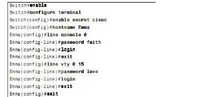
Securing the Switch CLI
To reach a switch’s enable mode, a user must reach user mode either from the console or
from a Telnet or SSH session, and then use the enable command.

To reach enable mode from a vty (Telnet or SSH), the switch must be configured with
several items:
■ An IP address
■ Login security on the vty lines
■ An enable password


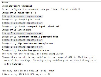
Configuring Usernames and Secure Shell (SSH)

Telnet sends all data, including all passwords entered by the user, as clear text.
SSH encrypts the data sent between the SSH client and the SSH server.

Step 1 Change the vty lines to use usernames, with either locally configured usernames
or an AAA server. "Login" command.

Step 2 Tell the switch to accept both Telnet and SSH with the transport input
telnet ssh vty subcommand. (The default is transport input telnet, omitting the ssh parameter.)

Step 3 Add one or more username name password pass-value global configuration commands to configure username/password pairs.

Step 4 Configure a DNS domain name with the ip domain-name name global configuration command.

Step 5 Configure the switch to generate a matched public and private key pair, as well as a shared encryption key, using the crypto key generate rsa global configuration command.

Step 6 Although no switch commands are required, each SSH client needs a copy of the switch’s public key before the client can connect.


Enable Mode Passwords
■ If the global configuration command enable password actual-password is used, it
defines the password required when using the enable EXEC command. This password
is listed as clear text in the configuration file by default.

■ If the global configuration command enable secret actual-password is used, it defines
the password required when using the enable EXEC command. This password is listed
as a hidden MD5 hash value in the configuration file.

■ If both commands are used, the password set in the enable secret command defines
which password is required.


Password Encryption
■ When the service password-encryption command is configured, all existing console,
vty, and username command passwords are immediately encrypted.

■ If the service password-encryption command has already been configured, any future
changes to these passwords are encrypted.

■ If the no service password-encryption command is used later, the passwords remain
encrypted, until they are changed—at which point they show up in clear text.


Banners
Cisco routers and switches can display a variety of banners depending on what a router or
switch administrator is doing. A banner is simply some text that appears on the screen
for the user.


Logging synchronous and exec-timeout Commands
To make using the console a little easier, you can tell the switch to display syslog messages
only at more convenient times, such as at the end of output from a show command or to
prevent the interruption of a command text input. To do so, just configure the logging
synchronous console line subcommand.

By default, the switch or router automatically disconnects users after 5 minutes of inactivity, exec-timeout minutes seconds, set the timeout to 0 minutes and 0 seconds, the router never times out the console .


Configuring the Switch IP Address
This interface plays the same role as an Ethernet interface on a PC.
In effect, a switch’s VLAN 1 interface gives the switch an interface into the default VLAN.


Port Security
Use port security to restrict that interface so that only the expected devices can use it.

Reduces exposure to some types of attacks in which the attacker connects a laptop to the wall socket that connects to a switch port that has been configured to use port security

Step 1 Make the switch interface an access interface using the switchport mode access
interface subcommand.

Step 2 Enable port security using the switchport port-security interface subcommand.

Step 3 (Optional) Specify the maximum number of allowed MAC addresses associated with the interface using the switchport port-security maximum number interface subcommand. (Defaults to one MAC address.)

Step 4 (Optional) Define the action to take when a frame is received from a MAC address other than the defined addresses using the switchport port-security violation {protect | restrict | shutdown} interface subcommand. (The default action is to shut down the port.)

Step 5A Specify the MAC address(es) allowed to send frames into this interface using the switchport port-security mac-address mac-address command. Use the command multiple times to define more than one MAC address.

Step 5B Alternatively, instead of Step 5A, use the “sticky learning” process to dynamically learn and configure the MAC addresses of currently connected hosts by configuring the switchport port-security mac-address sticky interface subcommand.


Shutdown—The port immediately is put into the errdisable state, which effectively shuts it
down. It must be re-enabled manually or through errdisable recovery to be used again.

■ Restrict—The port is allowed to stay up, but all packets from violating MAC addresses are
dropped. The switch keeps a running count of the number of violating packets and can send
an SNMP trap and a syslog message as an alert of the violation.

Protect—The port is allowed to stay up, as in the restrict mode. Although packets from
violating addresses are dropped, no record of the violation is kept.


VLAN Configuration
Cisco switch interfaces are considered to be either access interfaces or trunk interfaces.
Access interfaces send and receive frames only in a single VLAN, called the access VLAN.

Trunking interfaces send and receive traffic in multiple VLANs.

Step 1 To configure a new VLAN:
a. From configuration mode, use the vlan vlan-id global configuration command
to create the VLAN and move the user into VLAN configuration mode.

b. (Optional) Use the name name VLAN subcommand to list a name for the VLAN. If not configured, the VLAN name is VLANZZZZ, where ZZZZ is the four-digit decimal VLAN ID.


Step 2 To configure a VLAN for each access interface:
a. Use the interface command to move into interface configuration mode for each
desired interface.

b. Use the switchport access vlan id-number interface subcommand to specify the VLAN number associated with that interface.

c. (Optional) To disable trunking so that the switch will not dynamically decide to use trunking on the interface, and it will remain an access interface, use the switchport mode access interface subcommand.


Securing Unused Switch Interfaces
The recommendations for unused interfaces are as follows:
■ Administratively disable the interface using the shutdown interface subcommand.

■ Prevent VLAN trunking and VTP by making the port a nontrunking interface using the
switchport mode access interface subcommand.

■ Assign the port to an unused VLAN using the switchport access vlan number
interface subcommand.

CCNA: Operating Cisco LAN Switches

Cisco uses the same concept of a command-line interface (CLI) with its router products and
most of its Catalyst LAN switch products. The CLI is a text-based interface in which the
user, typically a network engineer, enters a text command and presses Enter.

The switch does what the command says, and in some cases, the switch replies with some messages stating the results of the command.

Cisco refers to a switch’s physical connectors as either interfaces or ports. Each interface
has a number in the style x/y, where x and y are two different numbers.

Cisco supports two major types of switch operating systems: Internetwork Operating
System (IOS) and Catalyst Operating System (Cat OS). Most Cisco Catalyst switch series today run only Cisco IOS, but for some historical reasons, some of the high-end Cisco LAN
switches support both Cisco IOS and Cat OS.


Switch Status from LEDs
When an engineer needs to examine how a switch is working to verify its current status
and to troubleshoot any problems, the vast majority of the time is spent using commands
from the Cisco IOS CLI.

However, the switch hardware does include several LEDs that provide some status and troubleshooting information.

For example, SYST LED
■ Off: The switch is not powered on
■ On (green): The switch is powered on and operational (Cisco IOS has been loaded)
■ On (amber): The switch’s Power-On Self Test (POST) process failed, and the Cisco
IOS did not load.

STAT (status) mode
■ Off: The link is not working.
■ Solid green: The link is working, but there’s no current traffic.
■ Flashing green: The link is working, and traffic is currently passing over the interface.
■ Flashing amber: The interface is administratively disabled or has been dynamically
disabled for a variety of reasons.


Accessing the Cisco IOS CLI
The switch CLI can be accessed through three popular methods—the console, Telnet, and
Secure Shell (SSH).
Two of these methods (Telnet and SSH) use the IP network in which
the switch resides to reach the switch. The console is a physical port built specifically to
allow access to the CLI.
SSH encrypts all data exchange, including login passwords; Telnet encrypts
nothing.


CLI Access from the Console
Every Cisco switch has a console port, which is physically an RJ-45 port. A PC connects to the console port using a UTP rollover cable, which is also connected to the PC’s serial port.

UTP rollover cable has RJ-45 connectors on each end, with pin 1 on one end connected to pin 8 on the other, pin 2 to pin 7, pin 3 to pin 6, and pin 4 to pin 5.

The default console port settings on a switch are as follows:
■ 9600 bits/second
■ No hardware flow control
■ 8-bit ASCII
■ No stop bits
■ 1 parity bit


User and Enable (Privileged) Modes
User EXEC mode, sometimes also called user mode, allows the user to look around but not break anything.

A more powerful EXEC mode called enable mode (also known as privileged mode or privileged EXEC mode). Enable mode is so named because the enable command is used to reach this mode.


Storing Switch Configuration Files
Cisco switches contain Random Access Memory (RAM) to store data while Cisco IOS is using it, but RAM loses its contents when the switch loses power.

The following list details the four main types of memory found in Cisco switches:
■ RAM: Sometimes called DRAM for Dynamic Random-Access Memory, RAM is
used by the switch just as it is used by any other computer: for working storage. The
running (active) configuration file is stored here.

■ ROM: Read-Only Memory (ROM) stores a bootstrap (or boothelper) program that is
loaded when the switch first powers on. This bootstrap program then finds the full
Cisco IOS image and manages the process of loading Cisco IOS into RAM.

■ Flash memory: Either a chip inside the switch or a removable memory card, Flash
memory stores fully functional Cisco IOS images and is the default location where the
switch gets its Cisco IOS at boot time.

■ NVRAM: Nonvolatile RAM (NVRAM) stores the initial or startup configuration file
that is used when the switch is first powered on and when the switch is reloaded.


Copying and Erasing Configuration Files


Initial Configuration (Setup Mode)

Wednesday, June 17, 2009

CCNA: Ethernet LAN Switching Concepts

Switches segment a LAN into separate parts, each part being a separate collision domain.
By creating a separate collision domain for each interface, switches multiply the amount of available bandwidth in the network.


The IEEE defines three general categories of Ethernet MAC addresses:
■ Unicast addresses: MAC addresses that identify a single LAN interface card.
■ Broadcast addresses: A frame sent with a destination address of the broadcast address
(FFFF.FFFF.FFFF) implies that all devices on the LAN should receive and process the frame.
■ Multicast addresses: Multicast MAC addresses are used to allow a dynamic subset of
devices on a LAN to communicate.


Primary job of a LAN switch is to receive Ethernet frames and then make a decision:
1. Deciding when to forward a frame or when to filter (not forward) a frame, based on the
destination MAC address
2. Learning MAC addresses by examining the source MAC address of each frame
received by the bridge
3. Creating a (Layer 2) loop-free environment with other bridges by using Spanning Tree
Protocol (STP)

The key to anticipating where a switch should forward a frame is to examine and
understand the address table. The table lists MAC addresses and the interface the switch
should use when forwarding packets sent to that MAC address.


How Switches Learn MAC Addresses
Switches build the address table by listening to incoming frames and examining the source
MAC address in the frame. If a frame enters the switch and the source MAC address is not
in the MAC address table, the switch creates an entry in the table. The MAC address is
placed in the table, along with the interface from which the frame arrived.


Flooding Frames

The process of sending frames out all other interfaces, except the interface on which the
frame arrived, is called flooding. Switches flood unknown unicast frames as well as
broadcast frames. Switches also flood LAN multicast frames out all ports.

Switches keep a timer for each entry in the MAC address table, called an inactivity timer.
The switch sets the timer to 0 for new entries.

Each time the switch receives another frame with that same source MAC address, the timer is reset to 0.

If the switch ever runs out of space for entries in the MAC address table, the switch can then remove table entries with the oldest (largest) inactivity timers.


Avoiding Loops Using Spanning Tree Protocol
LAN switches is loop prevention, as implemented by Spanning Tree Protocol (STP). Without STP, frames would loop for an indefinite period of time in Ethernet networks with physically redundant links. To prevent looping frames, STP blocks some ports from forwarding frames so that only one active path exists between any pair of LAN segments (collision domains).

To avoid Layer 2 loops, all switches need to use STP. STP causes each interface on a switch
to settle into either a blocking state or a forwarding state.

*Blocking means that the interface cannot forward or receive data frames.
*Forwarding means that the interface can send and receive data frames.


Internal Processing on Cisco Switches
1. Store-and-forward processing:
The switch must receive the entire frame before forwarding the first
bit of the frame. This allows the switch to check the FCS before forwarding the frame.

2. Cut-through processing:
Switch starts sending the frame out the output port as soon as possible. This reduces latency, but it also propagates errors. Because the frame check sequence (FCS) is in the Ethernet trailer, the switch cannot determine if the frame had any errors before starting to forward the frame.

3. Fragment-free processing:
The switch forwards the frame after receiving the first 64 bytes of the frame, thereby avoiding forwarding frames that were errored due to a collision.


Switches Decision Making
Step 1 Switches forward frames based on the destination address:

a. If the destination address is a broadcast, multicast, or unknown destination
unicast (a unicast not listed in the MAC table), the switch floods the frame.

b. If the destination address is a known unicast address (a unicast address found
in the MAC table):
i. If the outgoing interface listed in the MAC address table is different from the
interface in which the frame was received, the switch forwards the frame out
the outgoing interface.
ii. If the outgoing interface is the same as the interface in which the frame was
received, the switch filters the frame, meaning that the switch simply ignores
the frame and does not forward it.


Step 2 Switches use the following logic to learn MAC address table entries:

a. For each received frame, examine the source MAC address and note the
interface from which the frame was received.

b. If they are not already in the table, add the address and interface, setting the
inactivity timer to 0.

c. If it is already in the table, reset the inactivity timer for the entry to 0.


Step 3 Switches use STP to prevent loops by causing some interfaces to block,
meaning that they do not send or receive frames.


Collision Domains
A collision domain is a set of network interface cards (NIC) for which a frame sent by
one NIC could result in a collision with a frame sent by any other NIC in the same
collision domain.

For a single collision domain:
■ The devices share the available bandwidth.
■ The devices may inefficiently use that bandwidth due to the effects of collisions,
particularly under higher utilization.


Broadcast Domains
A broadcast domain is a set of NICs for which a broadcast frame sent by one NIC is
received by all other NICs in the same broadcast domain.
When a host receives a broadcast, the host must process the received frame. This means that the NIC must interrupt the computer’s CPU, and the CPU must spend time thinking about the received broadcast frame.


Virtual LAN
A LAN consists of all devices in the same broadcast domain.
Without VLANs, a switch considers all interfaces on the switch to be in the same broadcast
domain.

■ To create more flexible designs that group users by department, or by groups
■ To segment devices into smaller LANs (broadcast domains) to reduce overhead caused
■ To reduce the workload for STP by limiting a VLAN to a single access switch
■ To enforce better security by keeping hosts that work with sensitive data on a separate VLAN
■ To separate traffic sent by an IP phone from traffic sent by PCs connected to the phones


Roles of campus switches:
■ Access: Provides a connection point (access) for end-user devices. Does not forward
frames between two other access switches under normal circumstances.

■ Distribution: Provides an aggregation point for access switches, forwarding frames
between switches, but not connecting directly to end-user devices.

■ Core: Aggregates distribution switches in very large campus LANs, providing very
high forwarding rates.

CCNA: Fundamentals of IP Addressing

The main job of IP is to route data (packets) from the source host to the destination host.
Because a network might need to forward large numbers of packets, the IP routing process
is very simple. IP does not require any overhead agreements or messages before sending a
packet, making IP a connectionless protocol. IP tries to deliver each packet, but if a router
or host’s IP process cannot deliver the packet, it is discarded—with no error recovery. The goal with IP is to deliver packets with as little per-packet work as possible, which allows
for large packet volumes.


IP header


*A routing protocol learns routes and puts those routes in a routing table.
*A routed protocol defines the type of packet forwarded, or routed, through a network.

IP addresses consist of a 32-bit number, usually written in dotted-decimal notation. For
instance, 168.1.1.1 is an IP address written in dotted-decimal form; the actual binary version is
10101000 00000001 00000001 00000001.

Each decimal number in an IP address is called an octet. So, for an IP address of 168.1.1.1, the first octet is 168, the second octet is 1, and so on.


Classes of Networks
IP defines three different network classes for addresses used by individual hosts—addresses called unicast IP addresses. These three network classes are called A, B, and C. TCP/IP defines
Class D (multicast) addresses and Class E (experimental) addresses as well.

By definition, all addresses in the same Class A, B, or C network have the same numeric
value network portion of the addresses. The rest of the address is called the host portion of
the address.

Class A, B, and C networks each have a different length for the part that identifies the network:
■ Class A networks have a 1-byte-long network part. That leaves 3 bytes for the rest of
the address, called the host part.

■ Class B networks have a 2-byte-long network part, leaving 2 bytes for the host portion
of the address.

■ Class C networks have a 3-byte-long network part, leaving only 1 byte for the host part.


*The Valid Network Numbers column shows actual network numbers. Networks 0.0.0.0 (originally defined for use as a broadcast address) and 127.0.0.0 (still available for use as the loopback address) are reserved.


IP Subnetting


Three parts of an IP address (network, subnet, and host), are called classful addressing. The term classful addressing refers to how you can think about IP addresses—specifically, that they have three parts.


IP addresses called classless addressing. Instead of three parts, each address has two parts:
■ The part on which routing is based
■ The host part

Finally, IP addressing with subnetting uses a concept called a subnet mask. A subnet mask
helps define the structure of an IP address.


Host Routing
Hosts actually use some simple routing logic when choosing where to send a packet. This
two-step logic is as follows:

Step 1 If the destination IP address is in the same subnet as I am, send the packet directly
to that destination host.

Step 2 If the destination IP address is not in the same subnet as I am, send the
packet to my default gateway (a router’s Ethernet interface on the subnet).


Router Forwarding Decisions and the IP Routing Table


Step A
PC1 sends the packet to its default gateway.
Step B R1 processes the incoming frame and forwards the packet to R2.
Step C R2 processes the incoming frame and forwards the packet to R3.
Step D R3 processes the incoming frame and forwards the packet to PC2.


IP Routing Protocols

The routing (forwarding) process depends heavily on having an accurate and up-to-date
IP routing table on each router. IP routing protocols fill the routers’ IP routing tables with
valid, loop-free routes.
■ To dynamically learn and fill the routing table with a route to all subnets in the network.
■ If more than one route to a subnet is available, to place the best route in the routing table.
■ To notice when routes in the table are no longer valid, and to remove them from the routing table.
■ If a route is removed from the routing table and another route through another
neighboring router is available, to add the route to the routing table. (Many people view
this goal and the preceding one as a single goal.)
■ To add new routes, or to replace lost routes, with the best currently available route as
quickly as possible. The time between losing the route and finding a working replacement route is called convergence time.
■ To prevent routing loops.


Network Layer Utilities
■ Address Resolution Protocol (ARP)


■ Domain Name System (DNS)


■ Dynamic Host Configuration Protocol (DHCP)


■ Ping
Ping (Packet Internet Groper) uses the Internet Control Message Protocol (ICMP), sending a message called an ICMP echo request to another IP address. The computer with that IP address should reply with an ICMP echo reply.

Tuesday, June 16, 2009

CCNA: Fundamentals of WANs

OSI Layer 1 Point-to-point WANs
The big distinction between LANs and WANs relates to how far apart the devices can be
and still be capable of sending and receiving data. WAN connections typically run longer distances than Ethernet.

To create such long links, or circuits, the actual physical cabling is owned, installed, and
managed by a company that has the right of way to run cables under streets. Because a
company that needs to send data over the WAN circuit does not actually own the cable or
line, it is called a leased line.

Companies that can provide leased WAN lines typically started life as the local telephone company, or telco, generic term service provider.

Point-to-point WAN links provide basic connectivity between two points. To get a point-to-
point WAN link, you would work with a service provider to install a circuit. What the phone
company or service provider gives you is similar to what you would have if you made a
phone call between two sites, but you never hung up.

The telco seldom actually runs a 1000-mile cable for you between the two sites. Instead, it has built a large network already and even runs extra cables from the local central office (CO) to your building (a CO is just a building where the telco locates the devices used to create its own network).


Typically, routers connect to a device called an external channel service unit/data service
unit (CSU/DSU). The router cable and typically the CSU/DSU are owned by the telco’s customer, and the wiring to the CO and the gear inside the CO are owned by the telco. So, the telco uses the term demarc, which is short for demarcation point, to refer to the point at which the telco’s responsibility is on one side and the customer’s responsibility is on the other.

The device that provides clocking, typically the CSU/DSU, is considered to be the data communications equipment (DCE). The device receiving clocking, typically the router, is referred to as data terminal equipment (DTE).

*DCE cable needs to supply clock rate.

Customer premises equipment (CPE) refers to devices that are at the customer site,
from the telco’s perspective. For instance, both the CSU/DSU and the router are CPE
devices in this case.


Serial Cabling


WAN Speed
Original mechanism used for converting analog voice to a digital signal is called pulse
code modulation (PCM).

PCM defines that an incoming analog voice signal should be sampled 8000 times per second, and each sample should be represented by an 8-bit code.
So, 64,000 bits were needed to represent 1 second of voice.


OSI Layer 2 Point-to-Point WANs
High-Level Data Link Control (HDLC) and Point-to-Point Protocol (PPP)

HDLC
HDLC needs to determine if the data passed the link without any errors;
HDLC discards the frame if errors occurred. HDLC defines framing.

HDLC header includes an Address field and a Protocol Type field, with the trailer containing a frame check sequence (FCS) field.


PPP

PPP behaves much like HDLC. The framing looks identical to the
Cisco proprietary HDLC framing. There is an Address field, but the addressing does not
matter. PPP does discard errored frames that do not pass the FCS check.


Frame Relay and Packet Switching
Packet-switching service, physical WAN connectivity exists, similar to a leased line. However, a company can connect a large number of routers to the packet-switching service, using a single serial link from each router into the packet-switching service.

Two types of packet-switching service: Frame Relay and Asynchronous Transfer Mode (ATM).

Frame Relay, has many advantages over point-to-point links, particularly when you connect many sites via a WAN.
Frame Relay is cheaper. Frame Relay networks are multiaccess networks, which means that more than two devices can attach to the network.

A leased line is installed between each router and a nearby Frame Relay switch; these links are called access links.

The difference between Frame Relay and point-to-point links is that the equipment in the
telco actually examines the data frames sent by the router. Frame Relay defines its own
data-link header and trailer. Each Frame Relay header holds an address field called a data-
link connection identifier (DLCI).


Frame Relay switches are called DCE, and the customer equipment—routers, in this case—are called DTE.

DCE refers to the device providing the service, and the term DTE refers to the device
needing the frame-switching service. At the same time, the CSU/DSU provides clocking to
the router.

Frame relay virtual circuit, the logical path that a frame travels between each pair of routers.
Service provider preconfigures all the required details of a VC; these VCs
are called permanent virtual circuits (PVC). VCs share the access link and the Frame Relay network.

Frame Relay is designed with the concept of a committed information rate (CIR). Each VC has a CIR, which is a guarantee by the provider that a particular VC gets at least that much bandwidth.


When R1 needs to forward a packet to R2,
it encapsulates the Layer 3 packet into a Frame Relay header and trailer and then sends
the frame. R1 uses a Frame Relay address called a DLCI in the Frame Relay header,
with the DLCI identifying the correct VC to the provider. This allows the switches to
deliver the frame to R2, ignoring the details of the Layer 3 packet and looking at only
the Frame Relay header and trailer.

CCNA: Fundamentals of LANs

Carrier sense multiple access with collision detection (CSMA/CD) algorithm
CSMA/CD algorithm works like this:

Step 1 A device with a frame to send listens until the Ethernet is not busy.
Step 2 When the Ethernet is not busy, the sender(s) begin(s) sending the frame.
Step 3 The sender(s) listen(s) to make sure that no collision occurred.
Step 4 If a collision occurs, the devices that had been sending a frame each send a jamming signal to ensure that all stations recognize the collision.
Step 5 After the jamming is complete, each sender randomizes a timer and waits that long before trying to resend the collided frame.
Step 6 When each random timer expires, the process starts over with Step 1.

CSMA/CD does not prevent collisions, but it does ensure that the Ethernet works well even
though collisions may and do occur.

*Ethernet carrier sense multiple access with collision detection (CSMA/CD) logic is that collisions should be detected within the first 64 bytes of a frame.


Collision Domain
Defines the set of devices whose frames could collide. All devices on a 10BASE2, 10BASE5, or any network using a hub risk collisions between the frames that they send, so all devices on one of these types of Ethernet networks are in the same collision domain.

To avoid collisions, and to recover when they occur, devices in the same collision domain use CSMA/CD or Buffering.


Common Types of Ethernet


Ethernet UTP Cabling

The three most common Ethernet standards used today—10BASE-T (Ethernet),
100BASE-TX (Fast Ethernet, or FE), and 1000BASE-T (Gigabit Ethernet, or GE)—use
UTP cabling.

RJ-45 connector has eight Ethernet UTP Cabling specific physical locations into which the eight wires in the cable can be inserted, called pin positions, or simply pins.

Although RJ-45 connectors and ports are popular, engineers might want to purchase Cisco
LAN switches that have a few physical ports that can be changed without having to
purchase a whole new switch. Many Cisco switches have a few interfaces that use either
Gigabit Interface Converters (GBIC) or Small-Form Pluggables (SFP). Both are small removable devices that fit into a port or slot in the switch.

Ethernet Cable Standard


Straight-through Cable
- Host to Switch or hub
- Router to Switch or hub


Crossover Cable
- Switch to switch
- Hub to hub
- Host to host
- Hub to Switch
- Router to host


Full duplex/half duplex
Full duplex means that an Ethernet card can send and receive concurrently.With only the switch and one device connected to each other, collisions cannot occur. When you implement full duplex, you disable CSMA/CD logic on the devices on both ends of the cable.first half of the address identifies the manufacturer of the card is called the organizationally unique identifier (OUI). second half of the address being assigned a number that this manufacturer has never used on another card.


Ethernet addressing (MAC, Media address control 802.3)
Ethernet LAN addressing identifies either individual devices or groups of devices on a
LAN. Each address is 6 bytes long, is usually written in hexadecimal. Unicast Ethernet addresses identify a single LAN card. Computers use unicast addresses to identify the sender and receiver of an Ethernet frame.

First half of the address identifies the manufacturer of the card is called the organizationally unique identifier (OUI).

Second half of the address being assigned a number that this manufacturer has never used on another card.

Each LAN card comes with a burned-in address (BIA, 6-byte address assigned by vendor) that is burned into the ROM chip on the card.


IEEE defines two general categories of group addresses for Ethernet:

■ Broadcast addresses: The most often used of the IEEE group MAC addresses, the
broadcast address, has a value of FFFF.FFFF.FFFF (hexadecimal notation). The
broadcast address implies that all devices on the LAN should process the frame.

■ Multicast addresses: Multicast addresses are used to allow a subset of devices on a
LAN to communicate. When IP multicasts over an Ethernet, the multicast MAC
addresses used by IP follow this format: 0100.5exx.xxxx.


LAN Header Format


*Ethernet Frame Check Sequence (FCS)
field in the Ethernet trailer—the only field in
the Ethernet trailer—allows a device receiving an Ethernet frame to detect whether the bits
have changed during transmission.